The gatekeeper of reality is
quantified imagination.
quantified imagination.
Pyroc

Parts that were used for this particular Pyroc Prototype included:
|
|
|
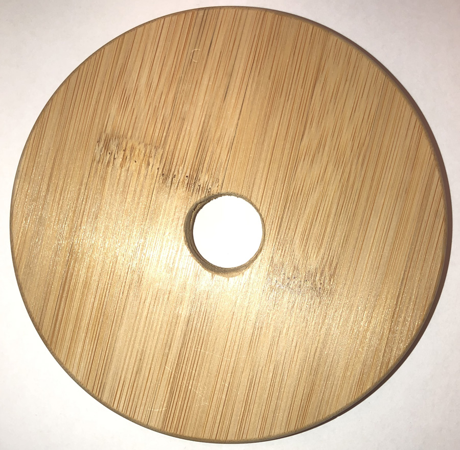
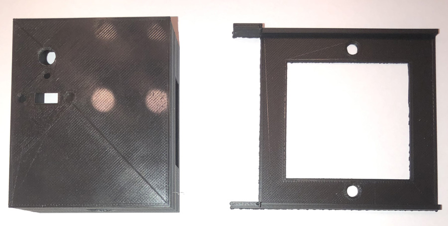
Drill a 1 inch hole in the container lid. |
|
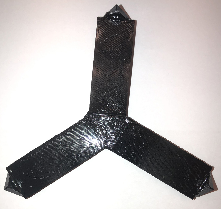
Glue together the base that the container will be placed on. |
|
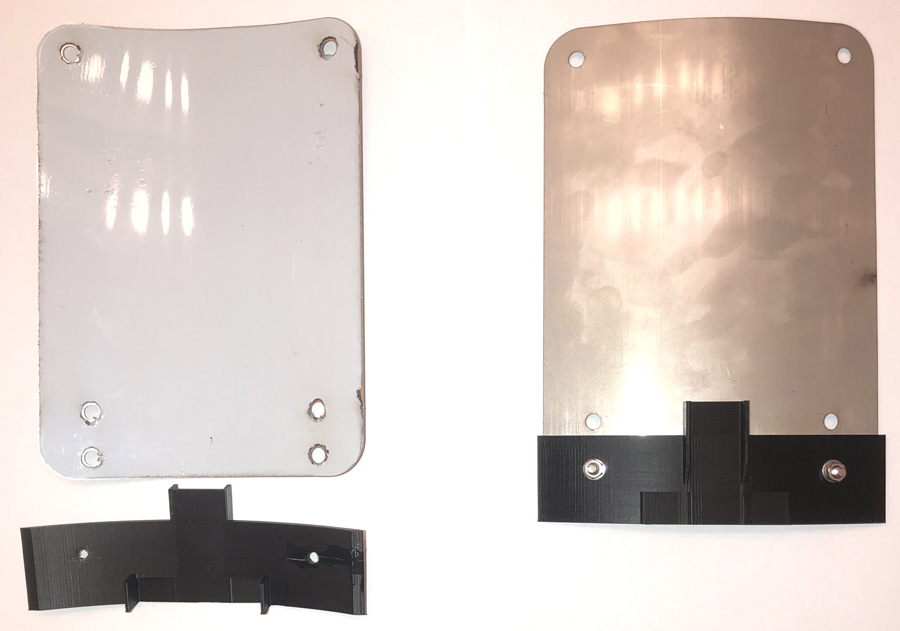
Glue the mirror base components together as shown. |
|
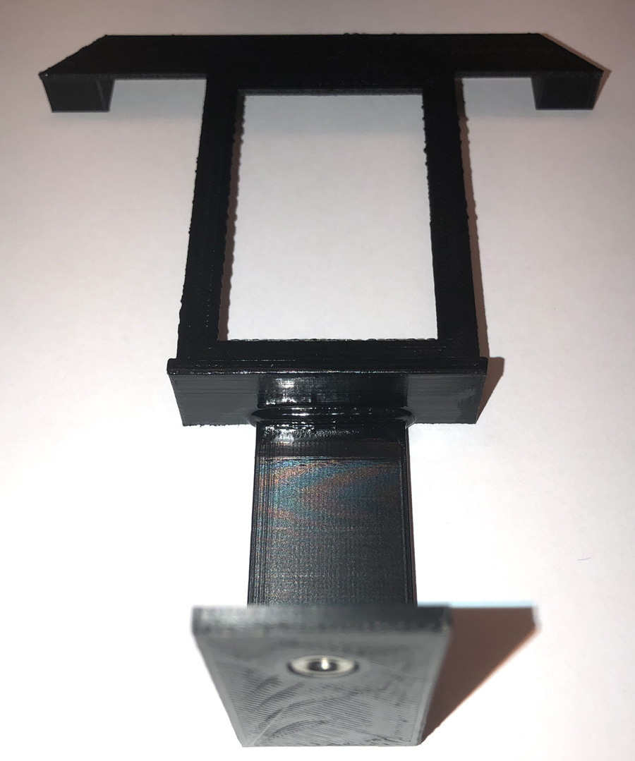
Place the M3 nut in the hole; you'll likely need a vice to seat the nut properly. |
|
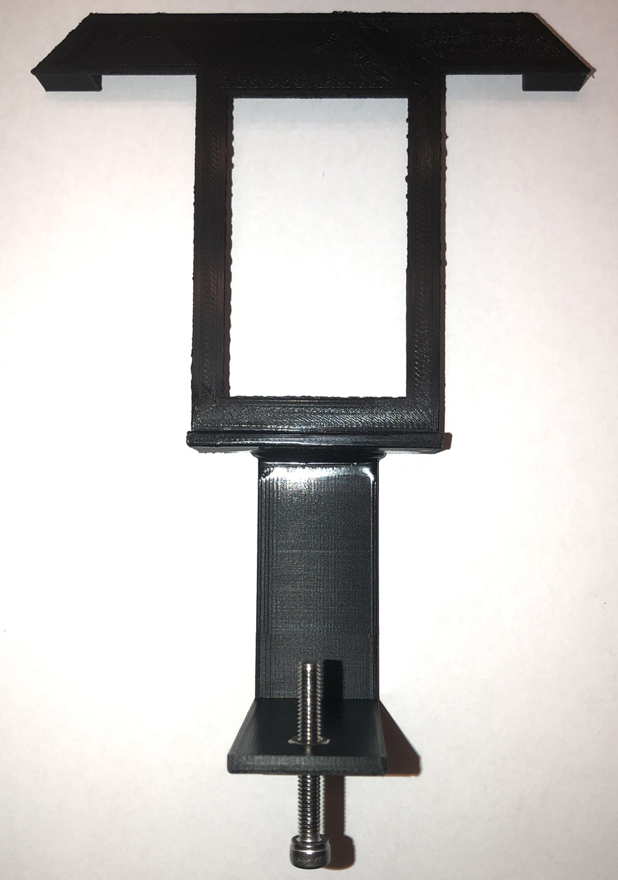
The flat mirror will need to be bent slightly so that it has the same shape as the mounting base, with the mirror side facing down. Then bolt the mirror to the mounting base. |
|
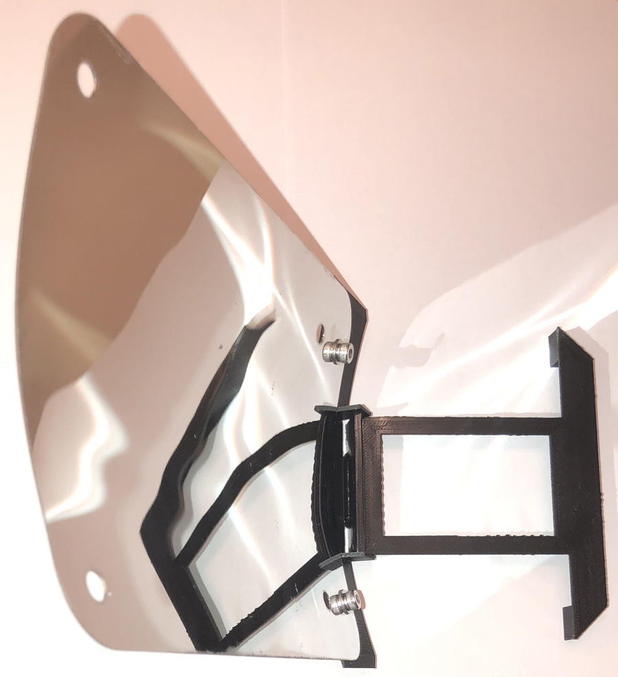
This view shows how the mirror mounting base would be placed in the mirror base with the long bolt. |
|
Glue the arms to the switch boxes. |
|
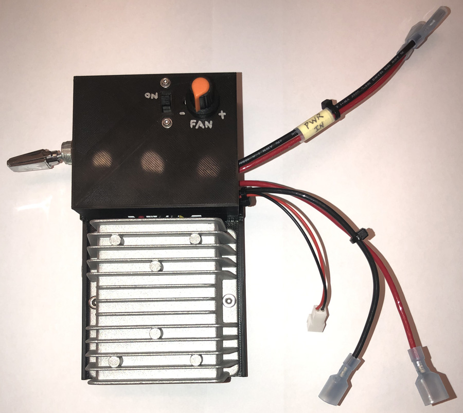
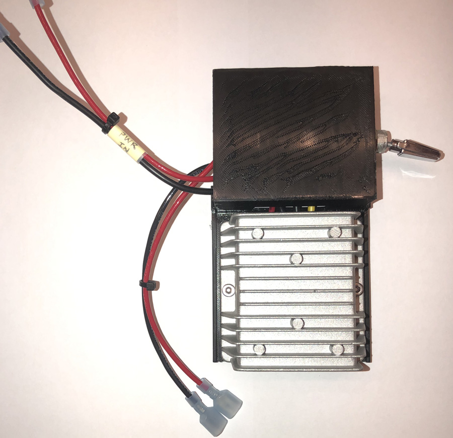
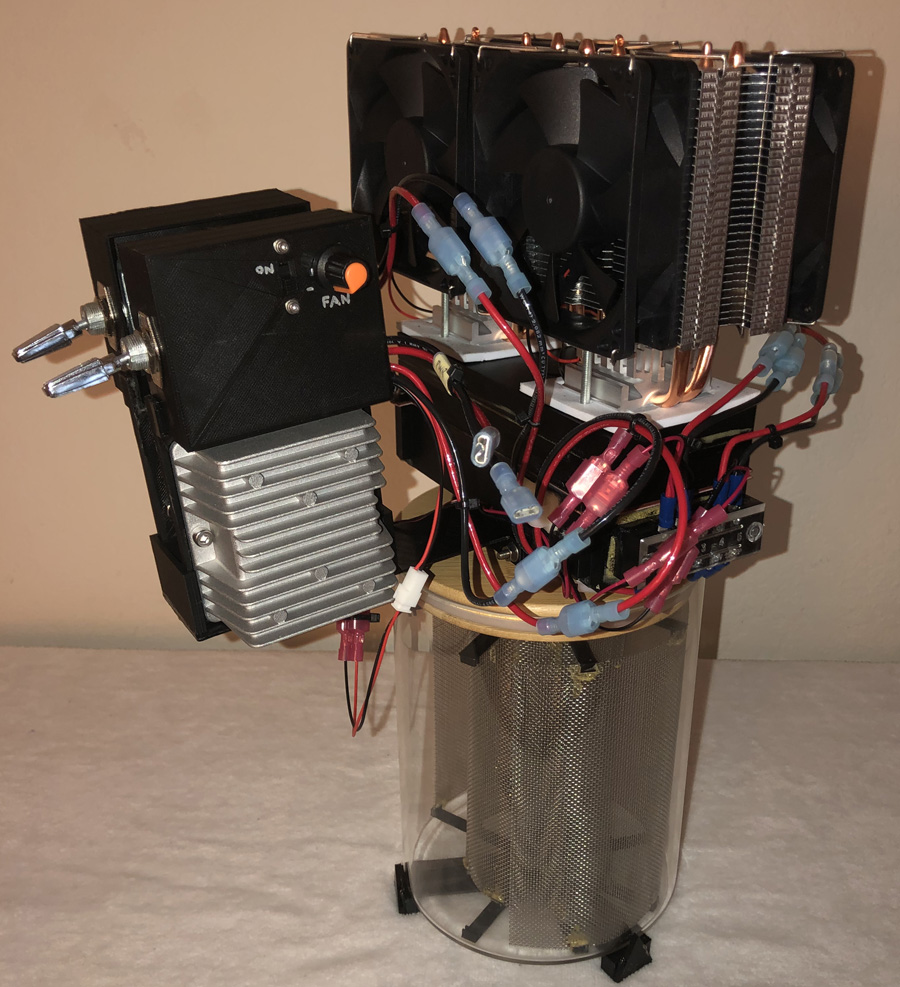
Wire up the large automotive switch so that it controls the power coming from the solar panels, with an output for one of the air conditioning systems, and an output for the small 30x10x10mm Brushless Turbo Blower whose power is controlled by a DPDT switch and a 1K potentiometer. |
|
Wire up the large automotive switch so that it controls the power coming from the solar panels, with an output for one of the air conditioning systems. |
|
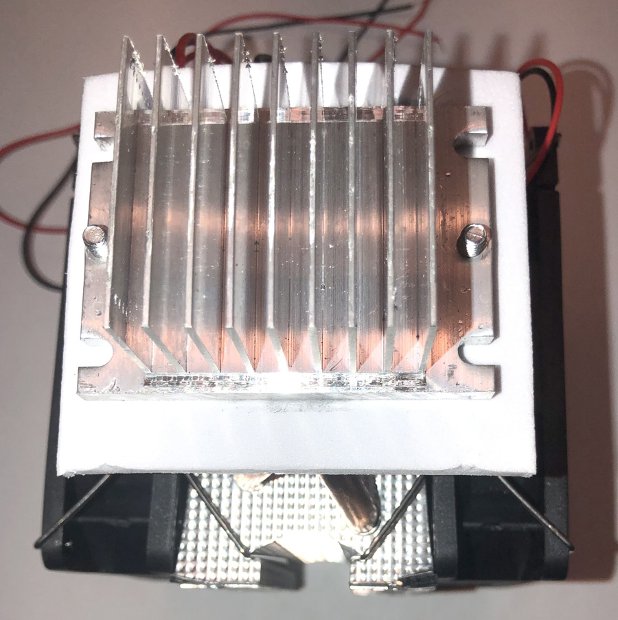
From each of the air conditioning systems, remove the small fan from the small cooling fins assembly. |
|
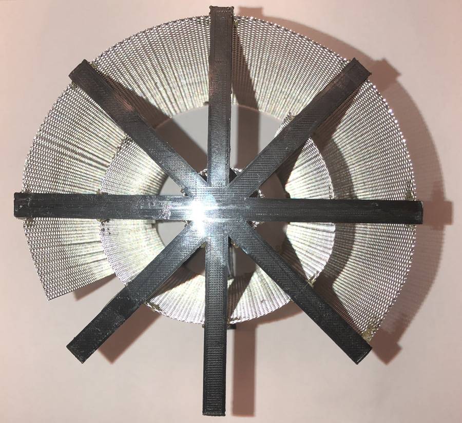
Form the stainless steel mesh sheet and glue to the star. The outer mesh sheet, as you can see, does not join which is okay; the gap allows sunlight to directly hit a portion of the inner sheet. That inner mesh sheet, too, has a gap between edges to allow more sunlight to hit the inner-most mesh sheet than what it would otherwise. Glue the other star to the opposite edge of the mesh sheets. |
|
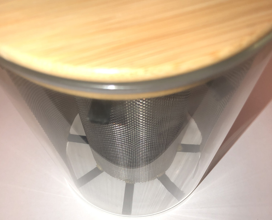
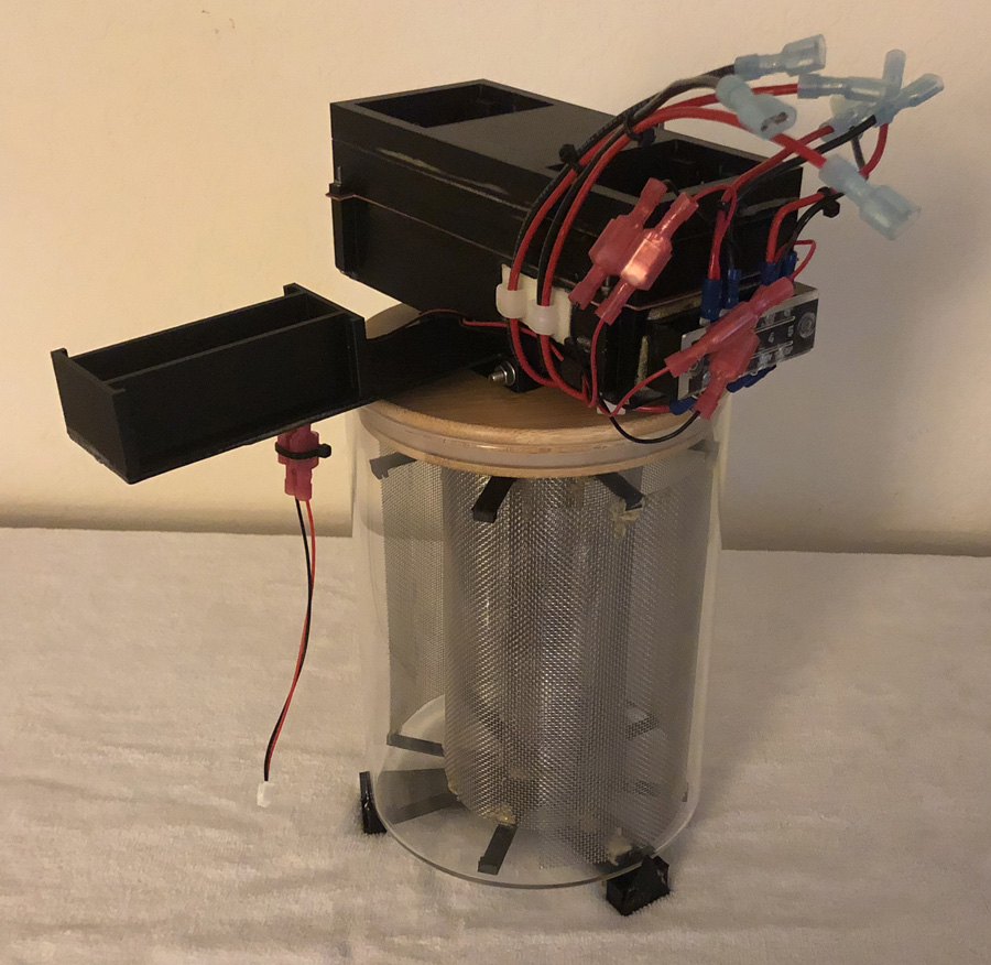
Insert the collector mesh into the container and place the lid on top of the container. |
|
Glue the switch case base to the long arm, on the flat side of the long arm. |
|
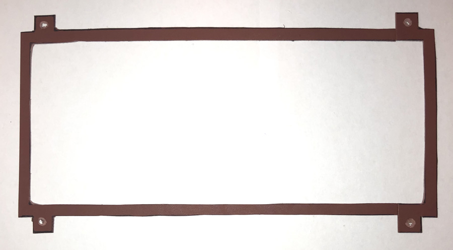
With some gasket material (available at most home improvement stores), trace and cut a gasket that will be placed between the spacer and the intake base. |
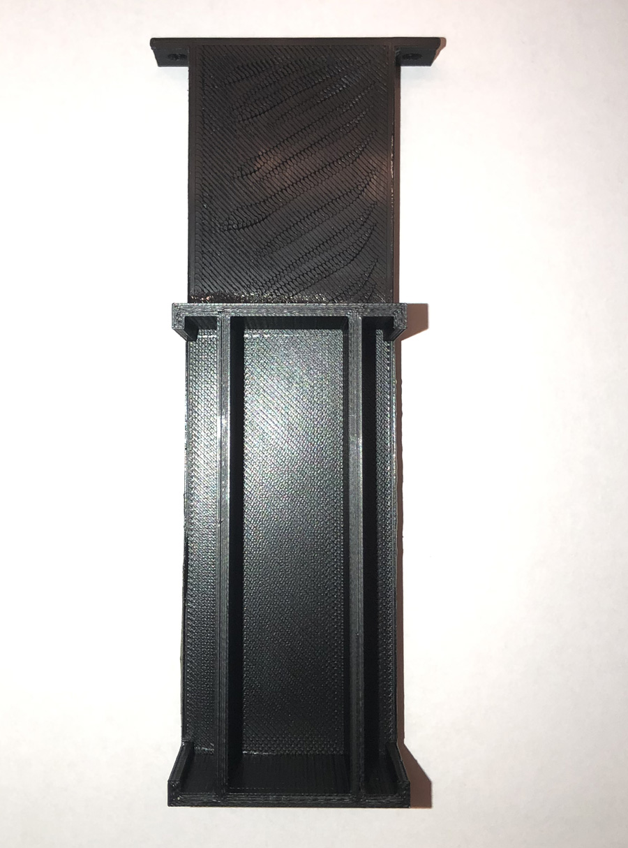
| Glue the spacer to the thick top cooler plate. The top cooler plate is what the two air conditioning systems are placed in. | |
|
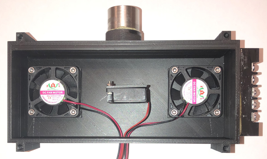
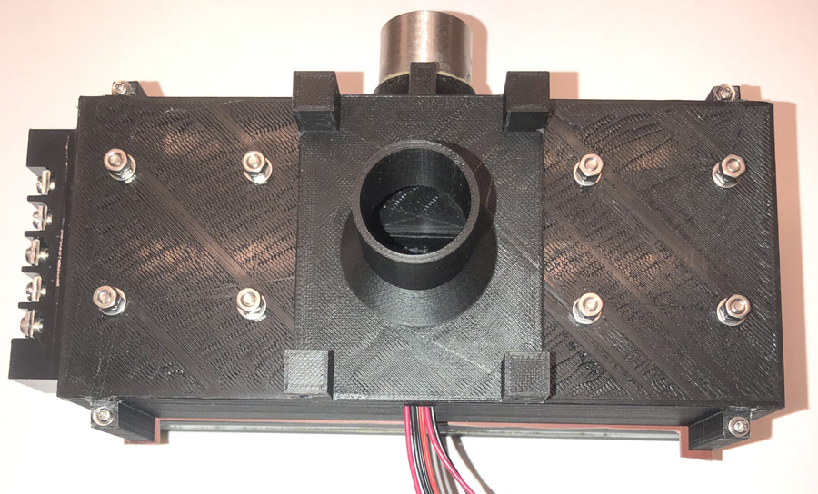
Place the two air conditioning system fans that you had removed into the intake base as shown and the smaller turbo blower in the center with M2 screws. |
|
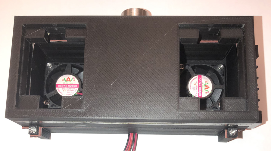
Place the gasket on top of the intake and place the spacer (that was glued to the thick top plate) on top of that and then bolt together. Depending on the length of the screws you use, you may need to trim part of the long screw guides so that the screw will go through the long screw guide and also have sufficient length to apply the bolt at the other end.
Using a sander or some other device to score part of the outer threaded pipe fitting, score about 1/4" of the surface edge. Then add glue to that surface area and push into the hole on the side of the intake. Don't forget to screw in the ball valve after the glue has dried. The ball valve allows you to control the amount of air to allow into the intake. |
|
Flip over the intake base and glue the funnel base to it. Be sure to position it so the two holes are opposite to where the valve controlled air intake is at.
After the glue has dried, bolt the switch case with the long arm (has two holes at the opposite end) to the intake base. |
|
Place the intake base onto the container lid so that the funnel goes into the hole on the lid. |
|
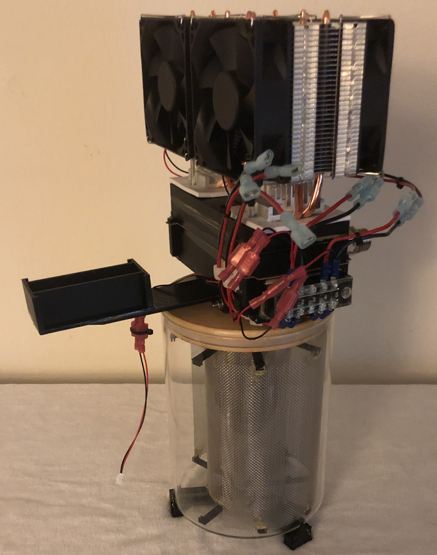
Seat the air conditioning systems into the top plate. The fit will be tight as the tolerance has only a few thousands of an inch of play to promote better sealing. |
|
Slip the switch cases into the switch case mount that was glued to the long arm, and make all the connections. |
|
This is an optional step but illustrates where the mirrors are placed around the resevoir. |
