(Enlarge)
|
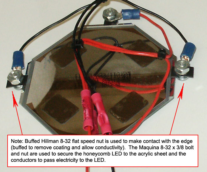
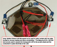
- The most precise "crafting" you will likely encounter is attaching the LED to the acrylic sheet (10" x 8"). The reason for this is that the LED has small surfaces that serve as contacts (no wire is attached to the LED).
- In order to attach the LED to the acrylic sheet I used what are known as flat speed nuts. These are metallic, flat pieces of metal and after removing the protective coating they become conductive (one for each side of the LED).
- After removing the coating I measured where to drill holes in the acrylic sheet, offset by the partial length of one of the flat speed nuts (see image).
- Following that the LED was attached to the acrylic sheet with the flat speed nuts "holding" the LED on each side.
- Wire is then attached to the screw followed by a nut to secure the wire to each flat speed nut.
- On the opposite side of the LED a section was cut out so that the batteries could be easily accessed (since this project uses multiple layers of acrylic sheet; see the third step for the cut-out area).
|
(Enlarge)
|
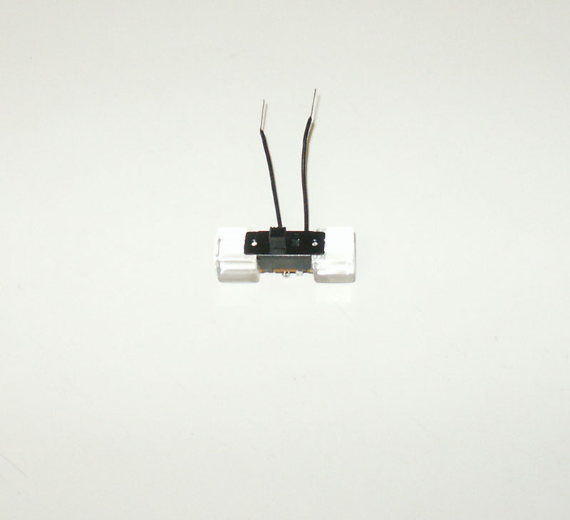
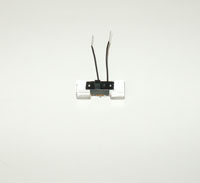
- You'll notice that I use three two position switches (1 SPST to control power to the LED, 1 SPST to control power to the digital voltmeter and 1 DPST switch to switch between using NiMh and Alkaline batteries).
- Before adding the switches, I glue them to two 1/4" acrylic cubes and solder on a starting length of wire. This will make adding the switch "assemblies" to be added without a lot of frustration.
|
(Enlarge)
|
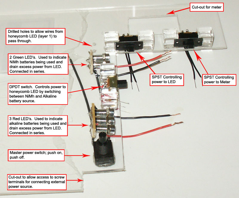
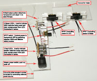
- The second layer acrylic sheet (the first layer is the layer with the LED attached to it), illustrates where I mount the switches, digital voltmeter cut-out, main push button power switch and the battery slot cut-out.
- You'll note that I have two green leds on one side of the DP switch and three red leds on the other side of the DP switch. The two green leds consume enough voltage from the battery pack to supply enough power to the LED (used when NiMh batteries are being used). The three red leds consume enough voltage to supply enough power to the LED (used when Alkaline batteries are being used). Without passing the power through the leds before the LED, you run the risk of burning out the LED because too much power is being supplied to it. Another reason for using 2 and 3 respectively is for power separation in the event of color blindness.
|

(Enlarge)
|
- Once the second layer is completed, return to the first layer (the acrylic layer with the LED).
- Be sure to drill out a hole for the push button main power switch.
- Here, after cutting out a section for the digital voltmeter, glue the digital voltmeter to the layer.
|
(Enlarge)
|
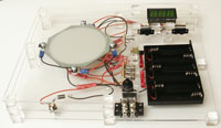
- On the third layer (a new acrylic sheet), drill a hole for the Coaxial Power Jack. Attach the Jack and the diode and connect wires to the battery pack wires. The battery pack consists of three double AA battery holders connected in series.
- Also glue the dual row connector to the battery pack and glue to the layer.
- Finally, glue the battery pack to the third layer and glue 1/4" acrylic cubes to the layer.
- Wire up the first and second layer of connections and also to the battery pack.
- Glue the second layer to the third layer. On top of the second layer glue more 1/4" acrylic cubes and glue the first layer to the second layer.
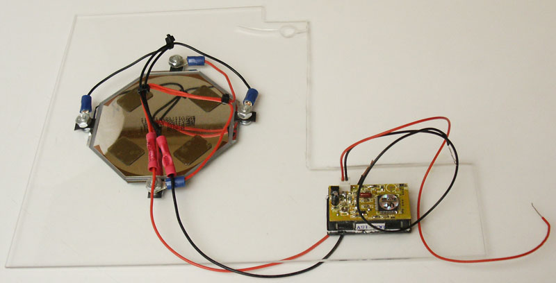
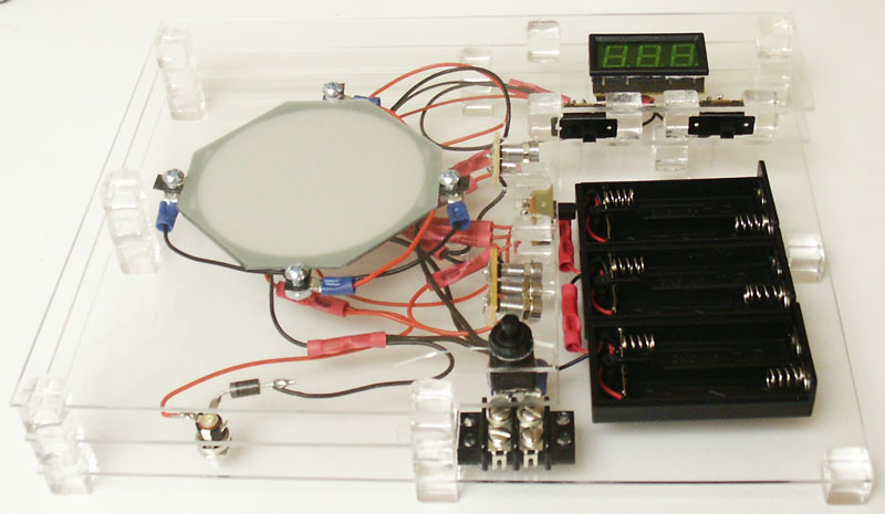
- Once assembled the project top view is shown by the image.
|

(Enlarge)
|
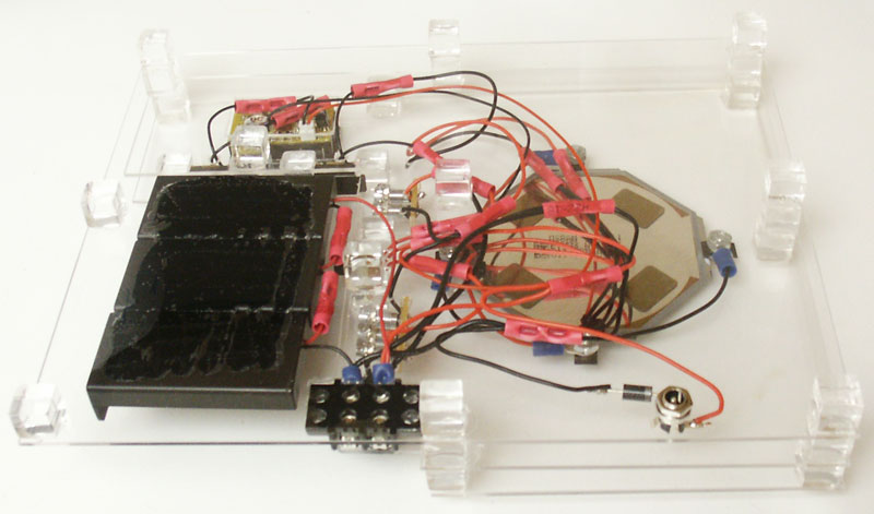
- This step shows the assembled project bottom view, mainly to show the Coaxial Power Jack area.
|

(Enlarge)
|
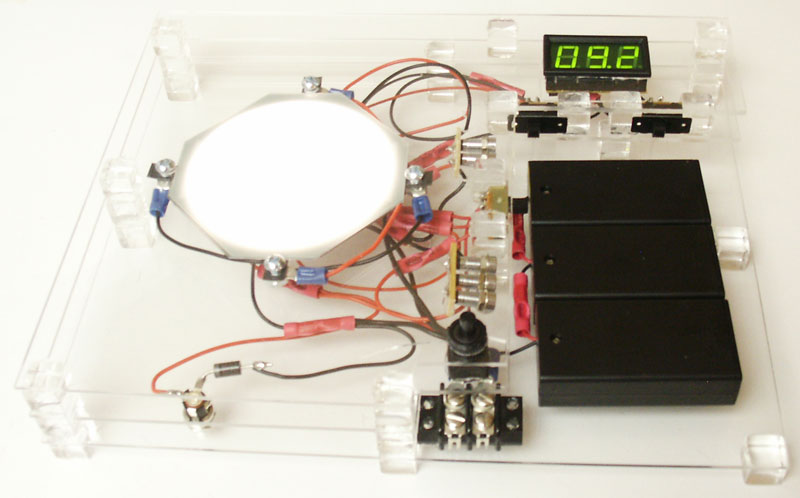
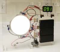
- This step illustrates the power on, with the digital voltmeter reporting the amount of voltage in the battery pack.
|
(Enlarge)
|
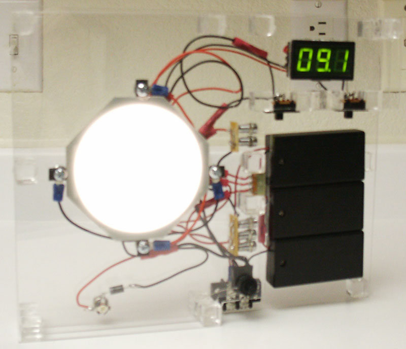
- This step illustrates the same as the previous step but with the unit on it's side.
- Having gone this far, the project is done!
|