The gatekeeper of reality is
quantified imagination.
quantified imagination.
Project "Build A Solar Panel"
|
Purpose The purpose of this project is to demonstrate how to build a solar panel from individual components (not to mention that I was curious). With the correct components, the cost of constructing a solar panel with longevity against environmental degredation can cost up to 30% less than commercial solar panels of the same Watt rating (not to mention that what you create, based on your assessment of the environment a solar panel would be used in, could actually be more resiliant than a "cookie cutter" manufactured solar panel). NOTE: Would you like to see how a solar powered entertainment center or power station is made? When you've finished with this page, please check out the solar powered entertainment center and power station tutorials. |
| Item | |
| 48 x 48 x 1/8 inch Acrylite UV stabilized transparent sheet; this is used in place of the glass top sheet (http://www.usplastic.com/catalog/item.aspx?itemid=30877&catid=442). Lexan could also be used. | |
| 48 x 48 x 3/16 inch ABS white sheet (http://www.interstateplastics.com/White-Abs-Extruded-Sheet-ABSWE.php) | |
| 72 x 1/4 x 1/4 inch clear extruded acrylic bar (http://www1.mscdirect.com/cgi/NNSRIT2?PMAKA=63392203&PMPXNO=1987563&cm_re=ItemDetail-_-ResultListing-_-SearchResults) | |
| Adhesive glue (http://www.filmtools.com/gorilla-glue-com-4-oz-052427500045.html) | |
| Silicone sealant/adhesive (http://www.sears.com/shc/s/p_10153_12605_03074317000P?i_cntr=1303782289177) | |
| Eight ounce Rosin core solder (http://www.radioshack.com/product/index.jsp?productId=2062713) | |
| SB540 - SB540 40V 5A Schottky Barrier Diode (http://www.futurlec.com/Diodes/SB540pr.shtml) | |
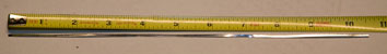
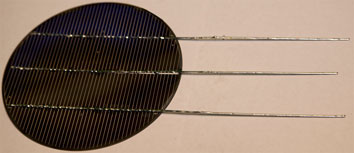
| .060 x .002 inch by 25 feet solar cell PV tinned interconnection ribbon (http://www.ec21.com/ks-tinned-copper-ribbon/) | |
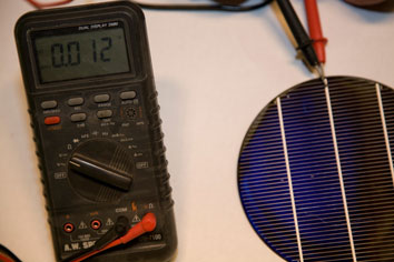
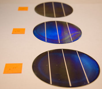
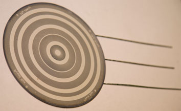
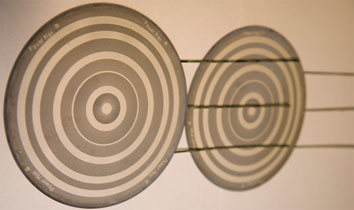
| Monocrystalline 6 inch (156mm) solar cell rated at .5VDC, 6 Amp Peak. You can get new 156mm solar cells in bulk from http://www.dmsolar.com; however, if you are interested in a set of 36 smaller solar cells, you can get a set from http://www.solarblvd.com/Solar-Cells-Solar-Cells/c128_130/p2390/Polycrystaline-5-x-5-Solar-Cells-36-Pieces-0.55-V/-5.2A/product_info.html. You could also try to locate solar cells from a seller at http://www.ebay.com or http://www.ecrater.com. | |
| Four position dual row barrier strip (http://www.radioshack.com/product/index.jsp?productId=2103982) | |
| Sixteen #8 insulated ring tongue terminals (http://www.radioshack.com/product/index.jsp?productId=2103306) | |
| Twelve gauge hookup wire black insulator (http://www.radioshack.com/product/index.jsp?productId=2062647) | |
| Twelve gauge hookup wire red insulator (http://www.radioshack.com/product/index.jsp?productId=2062646) | |
| 3 x 2 x 1 inch project enclosure box (http://www.radioshack.com/product/index.jsp?productId=2062279) | |
| Crimping tool (http://www.radioshack.com/product/index.jsp?productId=2062789) | |
| 40 Watt soldering iron (http://www.radioshack.com/product/index.jsp?productId=2062738) | |
| [OPTIONAL] Multimeter. About any DC voltage measuring capable multimeter will suffice. The DM9100 resembles what is actually used in this example (http://www.byramlabs.com/product_info.php/products_id/8184) | |
| [OPTIONAL] Variable temperature heat gun (http://www.milwaukeetool.com/tools/specialty-tools/heat-guns) | |
| [OPTIONAL] 28 square feet of .018 inch thick Ethylene Vinyl Acetate (EVA) sheet -OR- UV resistant Surlyn sheet. This is difficult to get in small quantities, but I have seen it available at http://www.ebay.com and http://www.ecrater.com. NOTE: EVA sheet shrinks as it is heated; hence 28 square feet is recommended versus 20 square feet. | |
 |
|
|
 |
|
|
 |
|
|
|
||
 |
|
|
 |
|
|
 |
|
|
 |
|
|
 |
|
|
 |
|
|
 |
|
|
|
||
|
||
|
||
|
||
|
||
|
||
|
||
|
||
 |
|
|
|
||
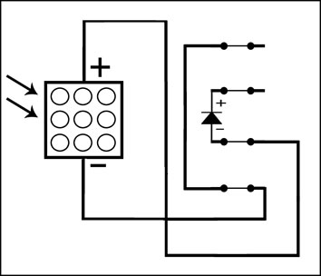
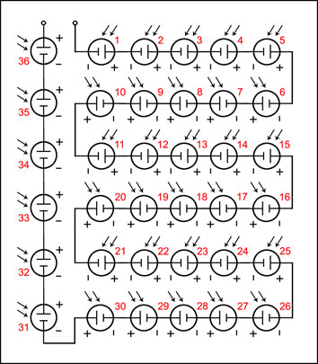
Scematic Diagram 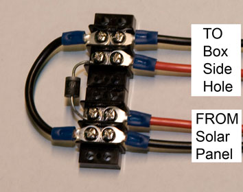
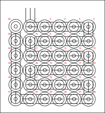
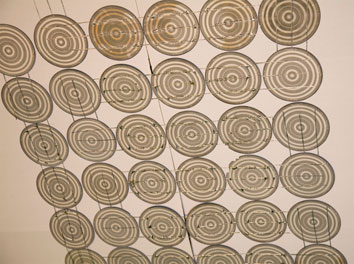
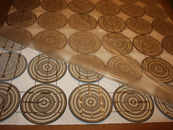
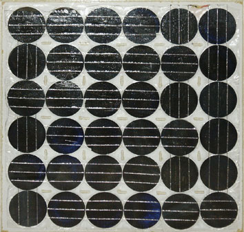
Visual Diagram |
|
|
|
||
